RM06J152CT 0603 1.5kΩ Datasheet: Specs & Sourcing Guide
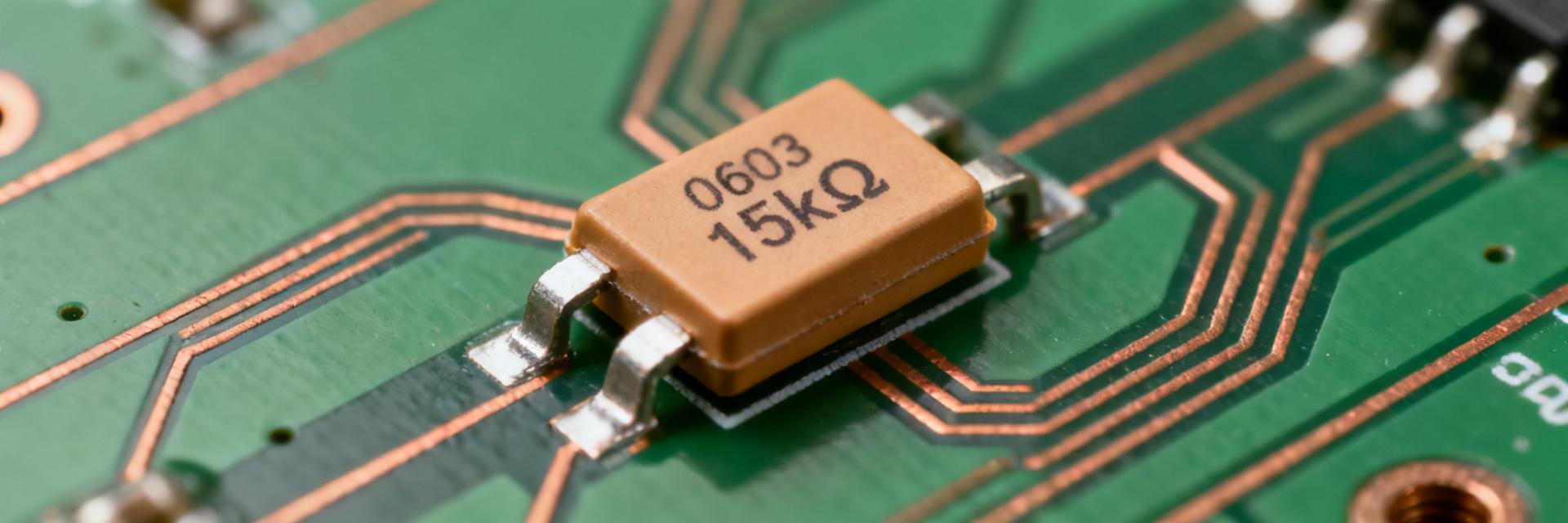
The RM06J152CT datasheet is a compact reference engineers use to validate 0603 1.5kΩ resistor performance for lead-time sensitive designs. Recent inventory volatility and BOM interruptions make tiny SMD passives critical: a single 0603 missing resistor can delay assembly lines. This introduction explains what follows—a concise datasheet walk‑through, exact 0603 footprint guidance, and practical sourcing/stock checks you can action today.
Readers will leave with the specific fields to extract from the part documentation, a verified pad recommendation for 0603 layouts, and a short checklist to capture stock availability metadata during procurement. The coverage is data-oriented and assumes the reader will confirm numeric values against the official RM06J152CT mechanical and electrical tables before release.
1 — Part background & quick overview

Decode the RM06J152CT part code
Point: RM06J152CT encodes package, resistance and series information important for BOM accuracy. Evidence: common reading is: RM06 = 0603 package family; 152 = resistance code (1.5 kΩ); trailing letters indicate tolerance, TCR, or series suffix. Explanation: confirm full part name, ordering codes, packaging (tape & reel or cut), and any internal suffix interpretation on the RM06J152CT datasheet before issuing PO to avoid cross‑ship errors.
Typical applications and selection rationale
Point: 0603 1.5kΩ parts are widely used where board density and cost matter. Evidence: typical use-cases include signal conditioning networks, pull‑ups/pull‑downs, and space‑constrained consumer electronics. Explanation: designers choose 0603 1.5kΩ for the balance of footprint, adequate power handling for low‑power signals, and low per‑unit cost; verify thermal margin for power‑dissipating applications to avoid derating issues.
2 — Electrical & performance specs to extract
Mandatory electrical specs from the RM06J152CT datasheet
Point: Key electrical parameters determine fit for purpose. Evidence: extract nominal resistance (1.5 kΩ), tolerance, power rating, maximum working voltage, TCR, and noise specifications. Explanation: measure and quote test conditions (typically 25 °C, specified measurement current/bridge method) and include them in procurement notes so test labs reproduce the same conditions when verifying performance.
| Parameter | Typical Value to Record |
|---|---|
| Nominal resistance | 1.5 kΩ |
| Tolerance | as specified (e.g., ±1%, ±5%) |
| Power rating | 0603 typical guideline ~0.0625 W (confirm datasheet) |
| TCR | ppm/°C (record value and test range) |
| Maximum working voltage | as specified on datasheet |
Reliability & environmental ratings
Point: Reliability columns and environmental statements indicate suitability for intended service. Evidence: capture operating temperature range, thermal shock, temperature cycling, moisture sensitivity level (MSL), and any life‑test data. Explanation: if the RM06J152CT datasheet quotes RoHS/REACH and reliability test methods, quote the exact datasheet language in procurement and failure analysis documents for traceability.
3 — Physical dimensions & 0603 footprint
Exact 0603 dimensions and metric equivalent
Point: Physical dimensions determine footprint and mechanical fit. Evidence: standard 0603 nominal dimensions are 0.06" × 0.03" (1.6 mm × 0.8 mm); thickness/height varies by series—confirm the RM06J152CT mechanical table. Explanation: always record dimensional tolerances and maximum height from the datasheet and compare to 3D models to avoid assembly and enclosure clashes.
Recommended PCB land pattern & assembly notes
Point: Pad geometry and stencil rules reduce defects. Evidence: use conservative pad sizes enabling a 0.2–0.3 mm solder fillet on each end and soldermask clearance to avoid bridging; follow recommended reflow thermal profile for the part family. Explanation: control tombstoning risk by ensuring symmetric pads, optimized paste coverage (~60–70% of pad), and proper conveyor/profile settings during reflow.
4 — Sourcing, pricing & stock availability
How to check real-time stock and lead time
Point: Up‑to‑date inventory data prevents surprises. Evidence: perform distributor inventory searches, request BOM snapshots from suppliers, and subscribe to lead‑time alerts. Explanation: capture stock availability metadata—availability date, MOQ, packaging format (reel/tape/cut), and shipment pack size—to make informed procurement choices and to log for future audits.
Pricing tiers, MOQ and supply-risk mitigation
Point: Pricing and MOQ drive cost and schedule decisions. Evidence: expect unit pricing on loose pieces versus substantial discounts on full reels; minimum reel quantities and MOQs vary. Explanation: mitigate constrained supply with split orders, approved alternates, staggered deliveries, and explicit alternate‑part entries on the BOM to reduce single‑source risk.
5 — Equivalents and design alternatives
How to find compatible substitutes
Point: Substitutes must match electrical and mechanical attributes. Evidence: require same package (0603), resistance value/tolerance, power rating, TCR, termination style, and equivalent footprint. Explanation: use a checklist to cross‑reference electrical specs, mechanical tolerances, and reliability claims; document verification steps and test sample results before approving an alternate for production.
When to redesign vs. accept a substitute
Point: Replacement vs. redesign depends on functional margins. Evidence: if power dissipation, precision, or thermal behavior differs, redesign the circuit or select a different series; if only availability differs, verify and approve a cross‑reference. Explanation: set decision rules in the engineering change policy: verify worst‑case thermal/power scenarios and document acceptable deltas for tolerance and TCR.
6 — Practical buying & PCB checklist
Pre-order checklist for procurement
- Confirm verified RM06J152CT datasheet reference and revision date.
- Specify packaging type (Tape & Reel, Cut Tape, Bulk).
- Verify minimum order quantity (MOQ) and shipment reel sizes.
- Review supplier lead-time estimates and standard return policies.
BOM and CAD deliverables for engineers
- Link primary manufacturer code directly to the CAD library asset.
- Ensure 0603 physical footprint layout conforms to standard IPC land patterns.
- Verify 3D step models are present and clear of mechanical housing boundaries.
- List multiple pre-approved alternate part numbers directly on the BOM.
Summary
Concise recap: the RM06J152CT datasheet reveals the electrical specs and test conditions to capture, the precise 0603 footprint actions to implement, and the stock availability metadata to record during sourcing. Next step: verify the RM06J152CT datasheet against your BOM, update footprint and procurement fields, and log current stock availability before issuing POs to avoid assembly delays.
Frequently Asked Questions
How is the RM06J152CT part number decoded?
The RM06J152CT part number encodes package size (RM06 for 0603 size), resistance value (152 representing 1.5kΩ using the standard three-digit system), and packaging details. Always verify the trailing letters for specific tolerance and temperature coefficient of resistance (TCR) ratings.
What are the key electrical parameters to verify on the RM06J152CT?
Engineers must confirm nominal resistance (1.5 kΩ), tolerance (typically ±1% or ±5%), power rating (typically 0.0625W / 1/16W for standard 0603), maximum working voltage, and Temperature Coefficient of Resistance (TCR).
What are the recommended footprint dimensions for a 0603 package?
The standard physical dimensions are 1.6mm x 0.8mm (0.06 inch x 0.03 inch). For the PCB layout, design symmetrical land patterns with appropriate solder mask clearances to achieve a 0.2-0.3mm solder fillet and minimize tombstoning risk during reflow.
How can supply chain risks be mitigated for the RM06J152CT resistor?
To mitigate risk, cross-reference compatible alternative manufacturers offering the exact same 0603 footprint, 1.5kΩ resistance, tolerance, and power ratings. Update the BOM with approved alternates and secure multi-sourced options early in the design phase.